Introduction To Networking: The OSI Networking Model
In the first section of this “Introduction To Networking” tutorial, we went over the very basics of networking; now it’s time for a look at the OSI networking model, which you can expect to see referenced multiple times on the CCENT, CCNA, and Network+ certification exams.
It’s also a major part of real-world networking, for reasons we’ll get into later in this tutorial. Right now, let’s have a look at this model as a whole.
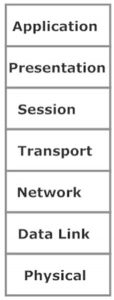
In our network admin role, we’re primarily concerned with the bottom three layers of this model. The top four layers work so well and so transparently that you can go a long time without even thinking about them – as a network admin, that is. As a future CCENT and CCNA, you need to think about all seven layers.
The uppermost layer of the OSI model (Layer 7), the Application layer is where our end users interact with the network. This layer performs two important behind-the-scenes tasks:
- Ensuring the remote communications partner or partner-to-be is available. After all, it takes two to tango and two to network.
- Ensuring the endpoints of any communication agree on basic rules, including data integrity, privacy, and the presence or absence of error recovery features. (More about that later.)
Moving down to Layer 6, the Presentation layer answers one basic question: “How should this data be presented?” If you’ve ever opened a PDF with a non-PDF-friendly app, you were likely presented with page after page of unreadable characters. That’s a Presentation layer issue. Data encryption takes place at L6 as well.
Layer 5, the Session layer, serves as the manager of the overall data transfer process. L5 handles the creation, maintenance, and teardown of the communications channel (the session) that exists between the two endpoints.
Things start to get interesting at Layer 4, the Transport layer. The main purpose of L4 is to establish a logical end-to-end connection between two systems. That’s obviously important, but it’s not the only L4 action. The Transmission Control Protocol (TCP) and the User Datagram Protocol (UDP) operate here.
(There’s a full TCP and UDP tutorial series over on my CCNA tutorials page!)
We network admins really start getting involved with things at Layer 3, the Network layer, because that’s where you’ll find these beauties:
That’s the universal symbol for a router, and L3 is where routers do their job using Internet Protocol (IP) addresses. Basically, the router’s job is to answer two questions:
- What valid paths exist from here to the desired destination?
- Of those valid paths, which is the best path to use?
At the Data Link layer, we’ll run into another very common network device.
This is the universal symbol for a switch, our main L2 device. Switches use Media Access Control addresses (MAC addresses) to get their job done. MAC addresses are often referred to by four other names:
- Layer 2 address / L2 address, referring to the layer at which the address is used
- Hardware address, because the MAC address is physically written into the hardware.
- Burned-In Address (BIA), since the address is burned into the hardware.
- Physical Address, because the address physically exists on said hardware.
Watch that last one. “Physical addresses” don’t run at the Physical layer, the bottommost layer of the OSI model. They run at L2.
No matter how complex our networks, in the end, it’s all about sending ones and zeroes across the Physical layer. Anything dealing with a network cable or the standards in use – including the pins, connectors, and the current itself – is running at L1.
The OSI model isn’t the only model in town, though. Time for a look at the TCP/IP network model!
You’ll knock out every binary and subnetting question on any Cisco and CompTIA certification exam once you’ve mastered my simple and effective subnetting methods!
Chris Bryant’s Binary and Subnetting Mastery Study Guide


